
February 16 2013
Other Articles Related to 3D Printing
Before we can get to the details of how to build a 3D model, we should go over a few basic 3D modeling concepts that apply to most 3D modeling software packages. While 3D animation and modeling software packages are complex, 3D printing usually only uses a subset of the package’s features.
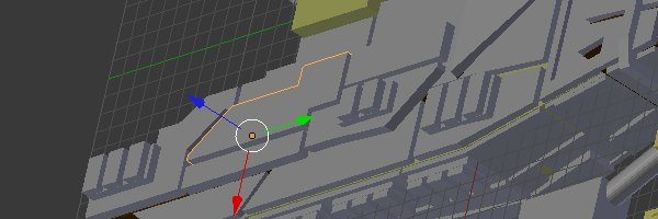
A typical 3D Model is built from many objects. An example of an object in a 3D model may be anything from an armor panel down to a single bolt on that armor panel. In the above image, a single object, in this case an armor panel, is highlighted in orange. An individual object consists of a mesh and properties about the object. A mesh is the actual physical shape of the object and its properties may dictate things like the color or texture of the object. For most 3D printing applications, the properties of the object do not matter. Only the shape of the mesh matters.
To help understand the details of a mesh, pick up a six sided die. Meshes are built from three types of pieces. The first type of piece is a face. Faces are the large flat surfaces all over the mesh. In the case of the six sided die, each of the six sides of the die is a face. Where a 3D model may differ from a real object is that the face of a 3D object may actually be built of many small faces which would be invisible to anyone not looking at the details of the mesh.
The second piece of a mesh is an edge. The line formed by the meeting two faces is an edge. Generally, the edges of a mesh are not manipulated directly, but they can be used for important purposes not related to 3D printing. In the above image, several edges are highlighted in red.
At the either end of an edge will be a vertex. In the case of a 3D printed model, every vertex will shared by at least two edges. Often times, a vertex will be shared by three or more edges. If this is not the case, your model may not be printable. Vertexes are important because in order to change the shape of a mesh, individual vertexes will be moved around. In the above image, four vertexes and their adjacent edges are highlighted in orange.
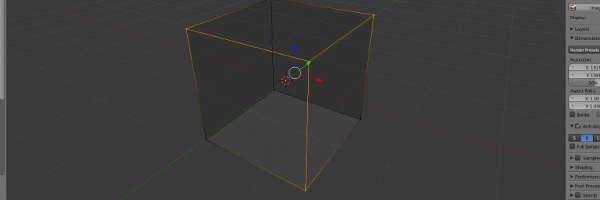
For 3D modeling purposes, meshes are generally altered in one of two ways: The entire mesh is manipulated or a individual vertexes are manipulated. Entire meshes can be moved around, rotated, or scaled. Moving a mesh changes it position relative to the other objects in the 3D model. Rotating the mesh will alter the direction that each of its faces are pointing. Scaling a mesh increases or decreases the size of the mesh.
Individual vertexes can be moved around to change the shape of an object. However, since a vertex has no size and no facing, rotating or scaling a single vertex will do nothing. Though if multiple vertexes are selected and a rotation or scale operation is performed, the position of these vertexes will be changed relative to one another based on the operation.
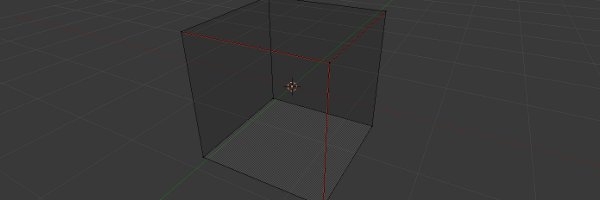
The last important concept to 3D Modeling is the Grid. Since 3D modeling exists in a 3D space, the grid will have 3 dimensions. These dimensions are commonly called X,Y, and Z and are the virtual equivalent of length, width, and height. Understanding these dimensions is important because when a mesh or vertex is being manipulated, often times, the manipulation is constrained to a single axis. This restriction makes the model construction process more precise.
In the next few articles dealing with how to use Blender, I will demonstrate all of the concepts discussed in this article.
